Fluorescent ballast circuit diagrams are used to control the amount of electricity that is sent to a fluorescent lamp. They are integral for the maintenance of a safe and efficient lighting system. As the use of fluorescent lighting becomes more popular, understanding the different components of a fluorescent ballast circuit diagram is essential for proper installation and maintenance.
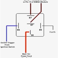
The basic components of a fluorescent ballast circuit diagram include three terminals: the input, output, and return. The input terminal is connected to the AC power source, while the output terminal is connected to the lamp. The return terminal is wired back to the AC power source. This configuration ensures that the lamp is receiving the correct amount of electricity.
In addition to controlling the voltage, a fluorescent ballast circuit diagram also performs other important functions. It controls the starting and ending of lighting, as well as providing an overvoltage protection system. This makes sure that too much voltage doesn’t flow through the system and potentially cause damage. Additionally, ballast circuits provide dimming capabilities, allowing for manual or automated control of brightness.
Overall, fluorescent ballast circuit diagrams are necessary for a fully functioning lighting system. Understanding their components and purpose is key to keeping your lighting system running smoothly. To ensure proper installation and maintenance, it is important to consult a professional electrician if you have any questions about the components of your ballast circuit diagram.

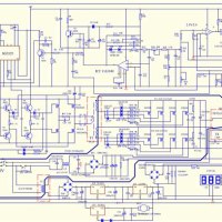
Electronic Ballast Working Principle Circuit Diagram Electrical4u

Espen Technology Inc

4 70w 1000v Dimmable Fluorescent Light Emergency Ballast Sanforce

Fluorescent Light Ballast Repair Replacement Wiring Connections Fix Flickering Dim Humming Buzzing Or Dead Lights

Research And Application Of Electronic Ballast Circuit Diagram

Fluorescent Lamp Electronic Ballast Circuit Under Circuits 57939 Next Gr

How Cfl Works Compact Electronic Ballast

F96t8 Fluorescent Ballast Electronic T8 59w

40w Fluorescent Lamp Electronic Ballast Circuit Under Circuits 58629 Next Gr

Mains 20 Watt Electronic Ballast Circuit Homemade Projects

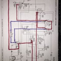
Rapid Start Ballast Lampholder Wiring 3 Lamps Electrical 101

Electronic Ballast For Fluorescent S 8 144w

Rapid Start Ballast Lampholder Wiring 2 And 4 Lamps Electrical 101

Typical Compact Flash Lamp Ballast Circuit 10 15 Fluorescent Scientific Diagram

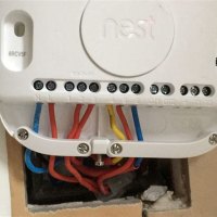
Light Connection Diagram

Typical Compact Flash Lamp Ballast Circuit 10 15 Fluorescent Scientific Diagram

Rapid Start Ballast Lampholder Wiring 2 And 4 Lamps Electrical 101

Fluorescent Light Ballast Repair Replacement Wiring Connections Fix Flickering Dim Humming Buzzing Or Dead Lights

Control Circuit Images For Free

How Cfl Works Compact Electronic Ballast