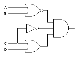
Logic gates are the heart and soul of digital circuit designs. With logic gate circuit diagram examples, engineers and developers can quickly and accurately create complex circuits that do exactly what they need them to do.
Understanding how these logic gates work is a vital part of being an electrical engineer or computer scientist, so it's important for professionals to understand the basics of how to create these diagrams. In this article, we'll cover some basic examples of logic gate circuit diagrams and explain how they work.
The simplest example of a logic gate is the AND gate. This type of gate is composed of two inputs and one output. The output will only be true if both the inputs are true. This makes it useful for determining whether two conditions have been met, such as whether a button has been pressed or a temperature has reached a certain level.
Another type of logic gate is the OR gate. This type of gate has two inputs and one output. The output will be true if either of the inputs are true. This makes it useful for creating a logical statement such as “if either A or B is true, then C is true”.
Inverters are another type of logic gate. These gates have one input and one output. The output is the opposite of the input. For example, if the input is false, the output will be true. Inverters are useful when you want to reverse the logic of a circuit, such as when you want to power a lightbulb when a button is not pressed.
Finally, there are also XOR gates, which stands for “exclusive or”. These gates have two inputs and one output. The output is true only if one of the inputs is true and the other is false. XOR gates are useful for situations where you need to know if one condition is true but the other is not.
By understanding the basics of these logic gate circuit diagram examples, engineers and developers can create sophisticated, reliable digital circuits. When used correctly, these gates can make the difference between a successful product design and a failed one. Using them correctly is essential for any digital engineer who wants to create reliable, efficient products.

Combinational Logic Circuits Definition Examples And Applications

Digital Electronics Logic Gates Basics Tutorial Circuit Symbols Truth Tables

I101 Introduction To Informatics Lab 7 Logic Circuits

Digital Logic Gates Electrical4u

Logic Gate Types Including Circuit Diagram Symbols And Uses

Designing Logic Circuits With Vhdl Sweetcode Io

Truth Tables Circuit Diagrams Of Logic Gates Your Electrical Guide

Logic Circuits Computer Science Gcse Guru

The 4081b Logic Circuit

Logic Gates

Basic Logic Gates Worksheet Digital Circuits

Digital Electronics Logic Gates Basics Tutorial Circuit Symbols Truth Tables

Xor Gate Circuit Diagram

Logic Gate Examples

Circuit Simplification Examples Boolean Algebra Electronics Textbook

Logic Gate Examples

Digital Electronics And Logic Circuits Role Of Transistors

Example Logic Circuit 1


