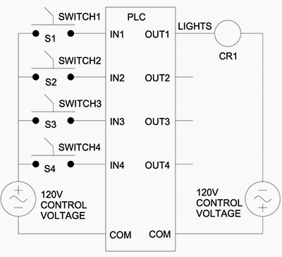
Plc Circuit Diagrams have become increasingly popular due to their ability to make complex automation projects easier to implement. The diagrams allow engineers and technicians to visualize the process they are trying to control before implementing it. For example, with a Plc Circuit Diagram, an engineer can easily see the number of inputs and outputs involved in a process, the connections between components, and the overall logical flow of the system. Today we'll explore why Plc Circuit Diagrams are so important and provide an example of one.
To understand why Plc Circuit Diagrams are beneficial, it's helpful to first look at how a Programmable Logic Controller (Plc) works. Essentially, a Plc takes signals from sensors and other devices and uses them to execute instructions from a program. The instructions tell the Plc when to turn on and off certain devices. If done manually, this could be a difficult and tedious process. However, by using a Plc Circuit Diagram, engineers and technicians can quickly design, debug, and monitor the process.
The example Plc Circuit Diagram provided here is a simple one that demonstrates the basic principles of a Plc. In the diagram, there is a temperature sensor, an output device such as a heater or air conditioner, and a connection to a Plc. The temperature sensor sends a signal to the Plc which then decides to turn the output device on or off based on the temperature reading. This basic circuit demonstrates how powerful Plc Circuit Diagrams can be.
Plc Circuit Diagrams are essential tools for engineers and technicians who want to create reliable and efficient automated systems. They provide a visual representation of a system and allow engineers and technicians to easily design, debug, and monitor the process. With a Plc Circuit Diagram, complex automation projects can be implemented with relative ease.

Boolean Logic For Ladder Diagrams Technical Articles

Simple Plc Program For Lighting Control System

How To Read A Plc Wiring Diagram Control Panel Upmation

Plc Timer Ladder Logic World

Examples

Basics Of The Plc Controllers Ladder Program Operations Blog Related To Automation Hmi Control Systems

Plc Ladder Logic Example Programs

Ladder Logic In Programmable Controllers Plcs Technical Articles

Plc Digital Input Module Circuit Diagram Engineers Community

Ladder Diagrams And The Plc For Electrical Engineers Beginners Eep

Plc Wiring Diagram P Pump M Motor T92s11d22 12 And Kuhp 11d51 Scientific

Ladder Logic Tutorial With Symbols Diagrams

Programmable Logic Controllers Plc Ladder Electronics Textbook

Plc Wiring Diagram Scientific

Basic Plc Ladder Programming Examples 23 Tutorial Point

Sequential Function Chart To Plc Ladder Logic Translation Dmc Inc

Plc Ladder Logic Examples Example 2 Engineering Arena

What Is Ladder Diagram Edrawmax Online

Advantech Wiring For Allen Bradley Plc Factory I O

How To Convert A Basic Wiring Diagram Plc Program Realpars


