Plc Panel Wiring Diagram Symbols: Understanding the Language of Automation
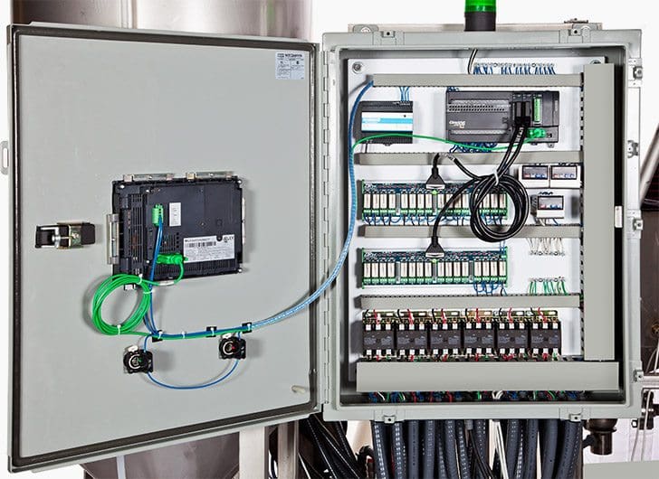
As automation continues to revolutionize commercial and industrial operations, the ability to read and understand Plc Panel Wiring Diagrams is an ever more critical skill. These diagrams are used to represent the wiring of a control system and make it easier for technicians to diagnose, troubleshoot, and work with new systems.
Plc Panel Wiring Diagrams are incredibly complex, but understanding the symbols is crucial for anyone who wishes to work in the field of industrial automation. Each symbol is designed to visually represent a particular component or type of connection within the system. By taking the time to learn what each symbol means, technicians can quickly identify where the problem lies and take the necessary steps to resolve it.
For instance, a common symbol used in Plc Panel Wiring Diagrams is the switch symbol. This symbol is composed of two rectangles connected by a line that indicates the power that is running through the switch. It is one of the most important symbols because it is used to indicate an on/off configuration. Additionally, this symbol can also depict multiple connections between various devices, making it a key piece of any technician’s arsenal.
Another important symbol used in Plc Panel Wiring Diagrams is the contactor symbol. This symbol is composed of two circles that represent two different contacts, as well as a line indicating the power running through the contactor. The contactor symbol is used to indicate that a device has two distinct operations which can be turned on and off separately. By understanding the significance of this symbol, technicians can effectively diagnose system issues and ensure that the system is functioning correctly.
Ultimately, the language of automation can be daunting for even the most experienced technician. However, by taking the time to learn the symbols associated with Plc Panel Wiring Diagrams, technicians can effectively diagnose and troubleshoot their systems. With the help of these symbols, technicians can quickly identify where the problem lies and take the necessary steps to resolve it.

The Basics Of Reading Plc Panels And Wiring Diagrams Do Supply Tech Support

Solidworks Electrical Professional

The Basics Of Reading Plc Panels And Wiring Diagrams Do Supply Tech Support

Basic Electrical Design Of A Plc Panel Wiring Diagrams Eep

How To Read The Electrical Diagram And What Are Symbols Involved In It Instrumentation Control Engineering

Electrical Panel Wiring Diagram

What Are Schematic Symbols Digikey

Plc Wiring Vfd Skills Hands On Electrical Training Amatrol

H1 Align Center Enotes Mechatronics And Controls

Electrical 2005 Cadalyst

Plc Training Reading Electrical Wiring Diagrams And Understanding Schematic Symbols Tw Controls

How To Wire A Plc Control Panel Instrumentation And Engineering

How To Convert A Basic Wiring Diagram Plc Program Realpars

Learn To Successfully Analyze Single Line Schematic P Id Logic And Wiring Diagrams Eep

Plc Wiring Diagram Symbols Archives Inst Tools
Electrical Schematic Symbols Plc Scada Dcs Automation Facebook

How To Read A Plc Wiring Diagram Control Panel Upmation

How To Read A Plc Wiring Diagram Control Panel Upmation

The Basics Of Reading Plc Panels And Wiring Diagrams Do Supply Tech Support


