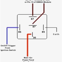
Understanding PMOS Circuit Diagrams
The PMOS circuit diagram is an essential tool for any electrical engineer. It is used to create and design digital circuits, which are the backbone of many modern devices. The PMOS circuit diagram provides a visual representation of the transistors, capacitors, resistors and other components that are used in digital circuits. The diagram makes it easy to analyze and design complex circuits, and it can also be used to troubleshoot faulty circuits.
PMOS stands for "positron field-effect transistor." This type of transistor is used to control the flow of current in a circuit. It can either turn on or off a current, depending on what voltage is applied to the gate. The PMOS transistor is often used in power supply circuits, where it can control the output voltage and current.
The PMOS circuit diagram includes several components. The first is the power source, which is usually a battery or other DC source. Next, there are the transistors, which are connected to the power source. Then, there are resistors and other components such as capacitors, which provide feedback and control the voltage and current output. Finally, there are the wires, which connect the components to each other.
When looking at a PMOS circuit diagram, it is important to pay close attention to the symbols associated with the various components. This will help to make sure that the correct connections are made. Additionally, the diagram should include a legend, which explains the different symbols and their meaning.
Once the PMOS circuit diagram has been understood, the electrical engineer should be able to identify the individual components and their function. This will allow them to design and troubleshoot circuits more quickly and effectively. Additionally, understanding the PMOS circuit diagram will help to ensure that the circuit is functioning properly and safely.
PMOS circuit diagrams are a key tool for any electrical engineer, and understanding how to read and interpret them is essential for success in the field. With a good knowledge of the diagram and its components, it is possible to design, troubleshoot and repair digital circuits with greater efficiency.

Adalm2000 Activity The Cmos Analog Switch Devices

Nmos Pmos Transistors Based On Dtmos Circuit Topology Scientific Diagram

Cmos Vs Mosfet The Main Difference Etechnog

Test Circuit For Acquisition Of Nmos And Pmos Characteristics Scientific Diagram

Mosfets For Load Switch Applications Onelectrontech

Shows The Circuit Diagram Of Folded Cascode Amplifiers With A Nmos Scientific

Solved The Circuit Diagram Of A Cmos Inverter Is Shown In Chegg Com

0 8um Cmos Process Learning Microelectronics

Results Page 215 About Remote Control Circuit By Motor Searching Circuits At Next Gr

Electronics Free Full Text Prototyping Of An All Pmos Based Cross Coupled Voltage Multiplier In Single Well Cmos Technology For Energy Harvesting Utilizing A Gastric Acid Battery Html

Vlsi System Design

Mosfet Transistors Nmos Pmos Symbols Structure Electronics Area

Image017 Jpg

Chapter 12 Field Effect Transistors 1 Nmos And Pmos 2 Load Line Analysis Of A Simple Amplifier 3 Small Signal Equivalent Ppt

Schematic Of A Pmos Vco And B Nmos Scientific Diagram

Solved Circuit Diagram Clearly Label The Source S Gate Chegg Com

Pmos Based Weighted Average Circuit A Schematic Of The Scientific Diagram

Cmos Javatpoint