Potentiometer Circuit Diagram Symbols
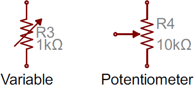
Potentiometers are a type of electronic component used to measure and control voltage, current, and resistance in circuits. As such, they are often seen in circuit diagrams, represented by a variety of symbols. Knowing what these symbols mean is essential for anyone who wants to understand how to read and build electrical circuits.
The most basic Potentiometer symbol looks like two arrows pointing in opposite directions. This symbol is used to represent the sliding contact of the potentiometer, which can be adjusted to vary the resistance in the circuit. It is usually placed near or within the power supply lines, and indicates the connection between the main power source and the potentiometer itself.
The second symbol commonly used to represent a potentiometer is a simple triangle with three circles around it. This symbol is more complex than the first, and represents the full potential-meter circuit. The three circles around the triangle represent the three terminals of the potentiometer: the positive terminal (V+), the negative terminal (V-), and the adjustable terminal (R), which is used to adjust the resistance of the circuit. This symbol is typically used when the position of the Potentiometer in the circuit needs to be specified.
Finally, there is a third symbol which is sometimes seen in schematic diagrams. This symbol is a circle with three lines radiating outward from it. This symbol is used to represent the three terminals of the Potentiometer, this time without representing the actual circuit. This symbol is typically used when the potentiometer’s position in the circuit does not need to be specified.
Overall, knowing the different Potentiometer circuit diagram symbols is important for anyone designing or building electrical circuits. With a firm understanding of the symbols and their meanings, you can ensure that your circuits work the way you want them to.

Potentiometer Symbol And Pinout Diagram Trim Rotary

Rotary Potentiometer

How To Read A Schematic Sparkfun Learn
Resistor Circuit Symbols Electronics Notes

What Is Potentiometer Diagram Symbols Characteristics Linquip

Potentiometer Working Circuit Diagram Construction Types

Potentiometer Working Circuit Diagram Construction Types

Potentiometer Variable Resistor
Basic Electric Guitar Circuits 2 Potentiometers Tone Capacitors Amplified Parts

Potentiometer Symbol And Pinout Diagram Trim Rotary

Electronic Symbol Potentiometer Resistor Wiring Diagram Schematic Electrical Network Transpa Png

How To Read A Schematic Sparkfun Learn

Rheostat Circuit Working Symbols And Its Applications

Potentiometer Construction Types Working Applications

Electric And Electronic Circuit Diagram Symbols Stock Ilration 56983158 Pixta

Electronic Circuit Symbols Components And Schematic Diagram

The Most Common Schematic Symbols In Electronics

Electronic Symbol Potentiometer Resistor Fixed Circuit Free Transpa Png Clipart Images

Potentiometer Symbol And Pinout Diagram Trim Rotary

Sparkfun Inventor S Kit Experiment Guide V4 1 Learn


