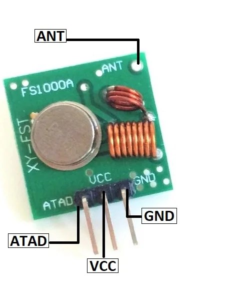
The use of RF Transmitter and Receiver (Tx and Rx) circuits is gaining in popularity as a way of sending and receiving data wirelessly between two nodes. These circuits are used in a wide range of applications including remote control, robotics, security systems, medical equipment, smart home devices, and many more. In this article, we will discuss the basic components required to construct a reliable RF Tx and Rx circuit, along with some of the key considerations to ensure a successful setup.
When constructing an RF Tx and Rx circuit, the two most important components are the transmitter and receiver chip. The transmitter chip takes the data signals as input and transmits them to the receiver chip placed at the remote node. The receiver chip then takes these signals and performs the necessary processing to extract the payload data. Depending on the application, the transmitted frequencies may vary; however, it is usually in the range of 300MHz to 3GHz.
In addition to the transmitter and receiver chips, the RF Tx and Rx circuit also requires an oscillator for generating the desired frequency, an amplifier for increasing the signal strength, a filter for avoiding interference from other signals, and an antenna for transmitting the signal. It is important to use quality components and properly design the circuit to ensure that the signals are sent and received without any interference. A proper circuit diagram should be created for proper wiring of the components and ensuring that the signal levels are within the desired range.
In conclusion, designing and building an RF Tx and Rx Circuit can be challenging, but with proper planning and knowledge, it is possible to construct a reliable and efficient circuit. Careful consideration of the components, frequency selection, wiring, and circuit diagram are all important factors to ensure the successful operation of the circuit. As the use of wireless technology continues to grow, having a reliable and well-designed circuit will become more and more important.

Rf Schematics

Simple Rf Remote Control Circuit Without Microcontroller

433 Mhz Rf 8 Appliances Remote Control Circuit Homemade Projects

Simple Rf Remote Control Circuit Without Microcontroller

433mhz Rf Transmitter And Receiver Circuit Freak Engineer

Rf Transmitter And Receiver Circuit Diagram

Radio Frequency Rf Remote Control Circuit Gadgetronicx

Making A 4 Channel Rf Remote Pcb Design Included Gadgetronicx

Radio Frequency Rf Remote Control Circuit Gadgetronicx

Simple Rf Remote Control Circuit Without Microcontroller

Wireless Rf Module Transmitter And Receiver Latest Applications

433mhz Rf Transmitter Pinout Features Applications Arduino Examples

Remote Control Circuit Through Rf Without Microcontroller

Rf Schematics

Remote Control Circuit Through Rf Without Microcontroller

Front Ends Of The Transmit And Receive Chains A Schematic Drawing Scientific Diagram

Sensors Free Full Text Rf Transceiver For The Multi Mode Radar Applications Html

Rf Remote Control Circuit


