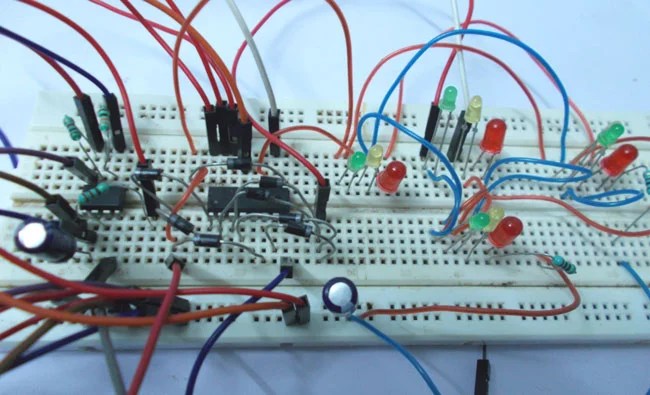
Traffic lights are an essential part of modern life. They help keep our roads safe and orderly by controlling the flow of traffic. But how exactly do they work? It turns out that traffic lights utilize a special type of electronic circuit that uses logic gates to create signals that control the flow of traffic.
Logic gates are electronic circuits used in digital logic applications. They are designed to accept one or more input signals and produce at least one output signal based on these inputs. The logic gates used in traffic lights are specifically designed to take multiple input signals from the traffic light sensors and then produce the appropriate output signal for each light. For example, if the traffic sensor detects a car approaching from the left, the logic gate will produce a signal that causes the left-facing light to turn green.
The process of designing traffic lights is both complex and important. Not only does it require creative problem solving and a working knowledge of logic gates, but also the ability to accurately predict the response of drivers in different scenarios. The logic gates must be programmed to detect various types of traffic, such as cars, buses, and trucks, and then be able to produce a signal that will cause the correct light to turn on. Additionally, the design must also account for the distance between the traffic lights and the vehicles and the speed of the vehicles.
Overall, traffic lights are a vital component of modern transportation infrastructure. Through the use of logic gates, engineers are able to create a reliable system that helps keep our roads safe. By understanding the basics of logic gates, it is possible to design efficient and effective traffic light systems that can help regulate the flow of traffic on our streets and highways.

Traffic Lights Controller Using Logic Gates 101 Computing

Digital Logic Design

Traffic Light Circuit Diagram Using 555 Timer Ic

Traffic Lights Tutorial Diagram Circuits Combination Logic Tutorials Electronic Hobby Projects

Traffic Light Project Using 555 Timer Ics

Solved Traffic Light System Uses Logic Gates As Part Of The Control When Output D Has Value Operaled This Happens Either Signal A Is Red Or

Traffic Light Controller Digital Systems Design Dr Ted Shaneyfelt Pdf Free

Sequential Logic Circuits

Traffic Light Controller Circuit Using Cd4027 Ne555

Arduino Traffic Light Controller System

Traffic Simple Under Repository Circuits 30305 Next Gr

Archaic Digital Design
Solved A Traffic Light System Uses Logic Gates As Part Of The Control Course Hero

Traffic Lights Circuit
Solved Traffic Light Junction Simulator Assignment Chegg Com

Breadboard 5 More Logic Joe S Hobby Electronics

4 Way Traffic Lights Circuit


