The difference between power circuits and control circuits revolves around what they are designed to do. While power circuits provide the electrical energy needed for a device to operate, control circuits are responsible for controlling its operation. In other words, a control circuit is like a switch telling the power circuit when to turn on and off.
To better understand this concept, it’s important to first think about how electricity works. It is composed of three main components: voltage, current, and resistance. Voltage is the amount of force that is pushing the electricity through the circuit, while current is the amount of electricity that is flowing through the circuit. Resistance is determined by the resistance of the material the electricity is running through. The combination of these three elements determines the power of the circuit.
Power circuits are typically more complex than control circuits since they need to be able to handle a larger amount of electricity. This means that power circuits will have thicker wires and a variety of components such as transistors, resistors, and capacitors. Control circuits, on the other hand, are simpler and will usually only contain a few components such as transistors and switches.
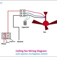
An example of a power circuit is an electric motor used to power a fan. The motor itself contains the power circuit, since it is the source of electricity that is pushing the fan blades to move. The control circuit then tells the motor when to speed up or slow down.
In conclusion, the difference between power circuits and control circuits is quite substantial. Power circuits are designed to supply the electrical energy necessary to run a device, while control circuits are used to control its operation. Understanding the fundamentals of how electricity works will help you better understand the differences between these two types of circuits.
What Is A Power Circuit And Controller Quora

Open Circuit How Does It Differ From Other Circuits Linquip

Understanding Differences Between Power And Ground Side Switching Technical Articles

Single Phase Power Systems Polyphase Ac Circuits Electronics Textbook
How Does A Power Circuit And Control Differ Quora

Motor Control Circuits Types Electrical Automation Plc Programming Scada Pid System

Troubleshooting Electric Motor Power Circuits Technical Articles

Troubleshooting Electric Motor Power Circuits Technical Articles

Difference Between Positive And Negative Feedback In Control System With Comparison Chart Circuit Globe

Solved 1 The Figure Qi Below Shows A Simplified Diagram Of Chegg Com

Troubleshooting Electric Motor Power Circuits Technical Articles

What Is Appa Power

Types Of Electric Circuit Definition Examples Symbols

Wiring In A Plc Control Panel Basic Electrical Design

Sequential Motor Control Circuit 3 Diagrams With Switch Timer Plc

Motor Control Circuit Wiring Inst Tools

Difference Between Series And Parallel Circuits With Its Practical Applications In Real Life
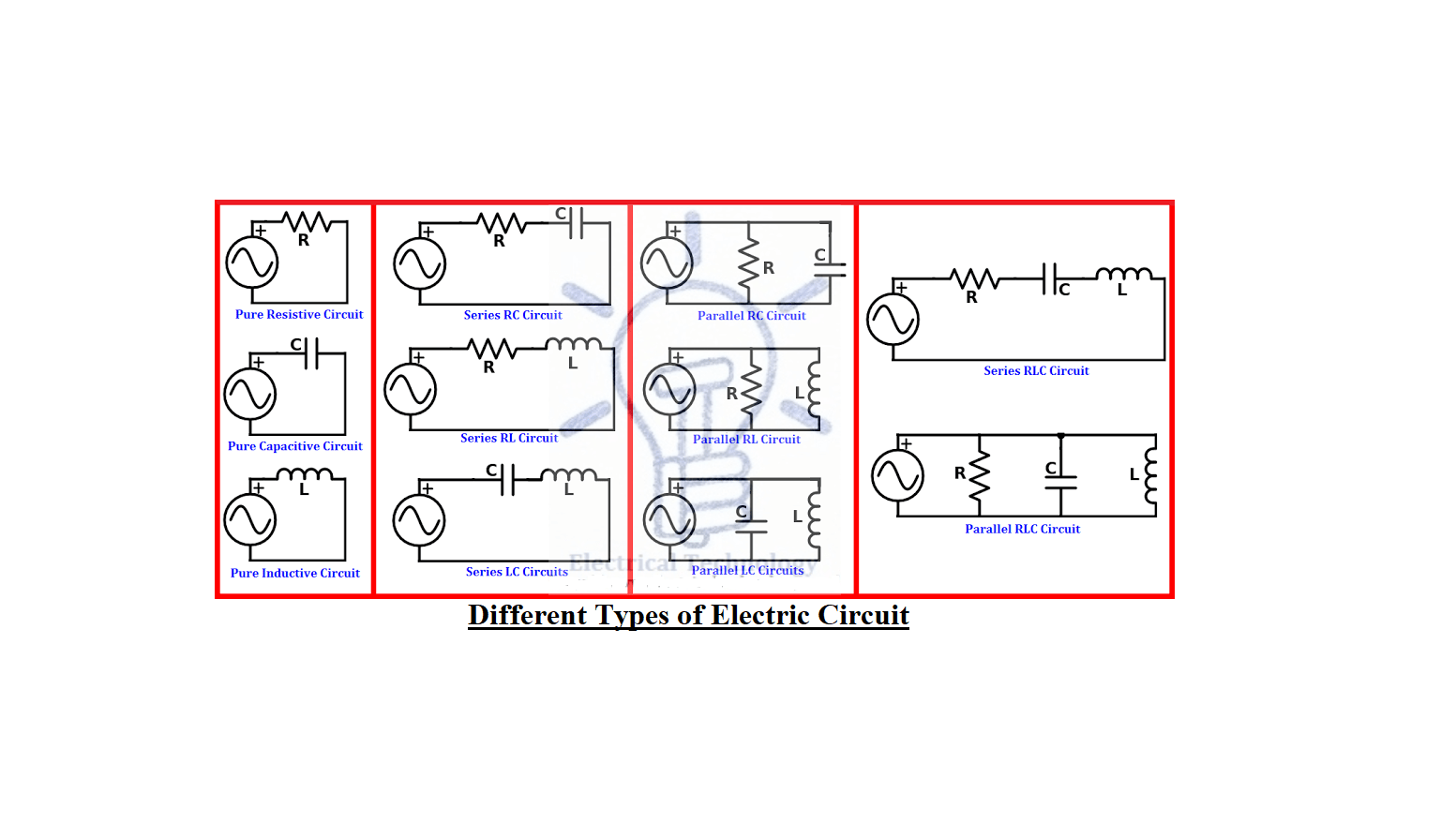
The 20 Types Of Electric Circuits Ultimate Guide In 2023 Linquip

Control Basics The Difference Between Sink And Source Logic

