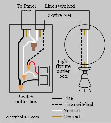
A wiring diagram photocell timer contactor is a complex system of wires, switches, and relays that allow for an automated control of an electrical circuit. In its most basic form, it consists of a photocell (a light-sensitive device), timer, and contactor (which controls the current flow). This system is often used in buildings and industrial settings to regulate lighting, air conditioning, and other electrical appliances. It is especially useful in areas where manual switching is inconvenient or when the lights need to be turned off at a certain time. Here, we explore what makes up a wiring diagram photocell timer contactor and how it works.
The wiring diagram photocell timer contactor is made up of three main components: the photocell, timer, and contactor. The photocell is connected to the timer. This allows the timer to sense when the light is on and off and adjust the contactor accordingly. The contactor then switches the current through the circuit and the lights go on or off, depending on the timer's settings. The timer can also be programmed for specific times, such as when it gets dark.
The wiring diagram photocell timer contactor is a great way to save energy by automatically controlling when lights and other electrical appliances are powered on and off. It is also ideal for commercial and industrial applications where maintaining accurate temperature and lighting levels are important. For example, it could be used during peak hours in a factory or office to make sure that the work environment is comfortable and safe. Additionally, the wiring diagram photocell timer contactor can be used to turn on and off security lights to keep intruders out and to automate circulation fans and ventilation systems.
Overall, the wiring diagram photocell timer contactor is an effective and efficient way to regulate lighting and other electrical appliances. Its combination of photocell, timer, and contactor allows for precise control and energy savings. Furthermore, this system is ideal for commercial and industrial applications, as it provides accurate and reliable control of temperature and lighting levels. Therefore, if you need a way to automate your circuits, a wiring diagram photocell timer contactor is the perfect choice.

How To Wire A Contactor 8 Steps With Pictures Wikihow
How To Design A Home Ats Using Contactors Quora
Lighting Contactors
Wiring Configuration And Wire Color Question Diagram For Photocell Magnetic Switch Manual Override Single Pole Diy Home Improvement Forum

Digital Time Switches Control And Automation Devices Modular Din Rail Products Abb
Selecting Effective Lighting Control White Paper

Photocell Based Night Light
Wiring Configuration And Wire Color Question Diagram For Photocell Magnetic Switch Manual Override Single Pole Diy Home Improvement Forum
Selecting Effective Lighting Control

Photocells Timers Electrical 101
Photocontrols Timers

Flip Flop Lighting System Diagram Archive Thctalk Com Cans Growing Forum Discussion Forums

How To Wire A Photocell Multiple Lights Theop Power Solutions
How To Wire Contactor Electrician Talk
Selecting Effective Lighting Control White Paper

How To Wire A Photocell Multiple Lights Theop Power Solutions

Does This Circuit Diagram Work Doityourself Com Community Forums


