A 3 Phase Capacitor Bank Wiring Diagram is an essential tool for anyone looking to install or maintain a three-phase electrical system. Three-phase systems are used in a variety of applications, including industrial processes, motor drives, and even residential power supplies. A 3 phase capacitor bank wiring diagram provides all the necessary information to ensure safe and efficient installation of the electrical components.
The basic components of a 3 phase capacitor bank wiring diagram include the individual capacitors, the connection terminals, the power source, the load, and the neutral ground. Each of these components must be correctly connected in order to create a safe and reliable system. The connection terminals are the most important element in the diagram, since they control the flow of electricity and determine how the capacitors will be wired in. The neutral ground is also an essential component, as it ensures that any stray voltage is grounded before it can cause damage.
When installing a 3 phase capacitor bank wiring diagram, it is important to follow the instructions provided by the manufacturer. This includes taking the proper safety precautions, such as using insulated tools and making sure all components are correctly wired. It is also important to double check all connections, and to test if the system is functioning correctly after installation. Additionally, regular maintenance should be done to ensure that the system is operating correctly at all times.
In order to ensure that the 3 phase capacitor bank wiring diagram is correct and working properly, it is important to understand the importance of the connection terminals. An incorrect connection may lead to unnecessary losses in power, and even cause fires. Therefore, it is important to follow the instructions carefully and to double-check all connections before turning on the power. Additionally, it is a good idea to keep spare parts of the wiring system on hand in case something does go wrong.
Overall, a 3 phase capacitor bank wiring diagram is an essential tool for anyone looking to install or maintain a three-phase system. By understanding the importance of the connection terminals, it is possible to ensure a safe and reliable system. Additionally, regular maintenance of the system is essential to ensure that the system is running smoothly and efficiently at all times.

Sustaility Free Full Text Improving The Efficiency And Of Power Systems Using Distributed Factor Correction Methods Html
Solutions For Power Factor Correction At Medium Voltage
Technical Specification

Connection Diagrams For Factor Correction Capacitors Kvar Guide

Capacitor Bank Wiring Modes Alpes Technologies

Externally F Shunt Capacitor Bank And Unit Scientific Diagram

Electricveda Com Capacitor Banks In Electrical Construction Works
Thyristor Switch Module Vtsm For Capacitor Bank
Ge High Voltage Capacitor And Equipment

Defining Size And Location Of Capacitor In Electrical System 1 Eep

China 3p 630a Ats Wiring Diagram Automatic Transfer Switch For Portable Generator Changeover

Item Vs 100 Hp 230v Voltage Ilizer On Phase A Matic Inc

Keltron Three Phase Tibcon Power Capacitor 10 0 Kvar Rs 1850 Id 15401466748

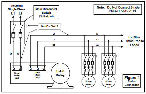
How To Install H A S Rotary Phase Conversion System
Zero Cross Over Turn On Thyristor Switch Card For Capacitor Bank Tsc 306 S 303 D Description
Capacitor Bank Switching And Hmi Subsystem Reference Design For Automatic Power Factor Controller Rev A
Power Factor Controller Rvt The Smart Pfc For Automatic Capacitor Bank

Capacitor Bank Wiring Modes Alpes Technologies

Içerik Animasyon Riskli 3 Phase Capacitor Bank Wiring Diagram Tasarotomotiv Net


