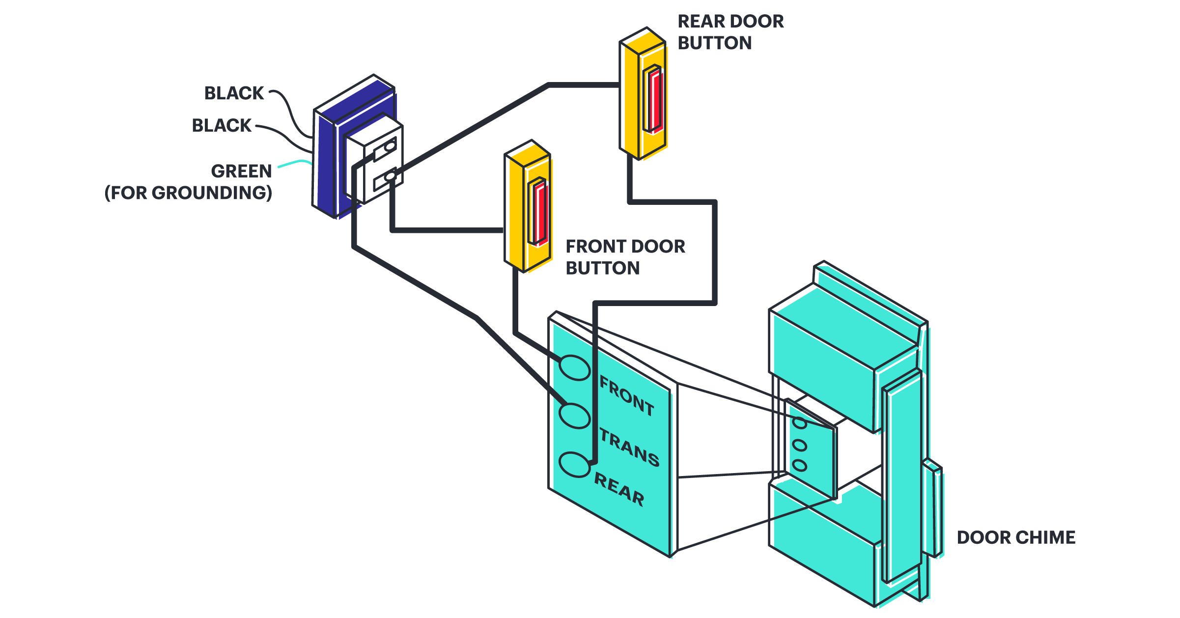
Basic Schematic Diagrams are a crucial tool for any engineer, technician, or electrician needing to understand how electrical components are wired together. These diagrams are used throughout the world of electrical work and are integral in almost every stage of the build process. Understanding how a circuit works requires a basic understanding of schematic diagrams.
A schematic diagram is a visual representation of an electrical circuit. It shows the components of the circuit as abstract shapes and the wires connecting them. The symbols used in these diagrams are standardised for each component and the lines show the connections between them. This makes it easier to read and understand the circuit’s purpose and how it works.
One of the most common uses of schematic diagrams is to help troubleshoot a circuit. By looking at the diagram, you can see which components are connected where and what voltages they are receiving. This makes it easy to pinpoint any problems that may be present. It can also be used to design new circuits, as the diagram can be used to check the correct wiring and connections before powering the circuit on.
To make sure the circuit performs correctly, attention must be paid to the accuracy of the schematic diagram. To ensure that this is done properly, there are many tools available to help. For example, electrical design software like Kicad or Autocad can be used to create accurate diagrams. Additionally, some manufacturers provide schematic diagrams for their products, which can be used to check the wiring of the device.
Schematic diagrams are an invaluable tool in the world of electronics. Being able to read and understand them is essential for anyone working with electrical components. Fortunately, modern tools make it easier to create and edit these diagrams, making it easier to diagnose and repair problems quickly.

Schematic Diagram Example Free Template Figjam

How To Read Electrical Schematics Circuit Basics

Difference Between Pictorial And Schematic Diagrams Lucidchart Blog

What Is The Meaning Of Schematic Diagram Sierra Circuits

Electronic Diagrams Prints And Schematics Instrumentation Tools

What Is The Meaning Of Schematic Diagram Sierra Circuits

How To Draw A Schematic Diagram Inst Tools

What Is The Meaning Of Schematic Diagram Sierra Circuits

Schematic Diagram Of The Electronic Circuit In 22 Inspired By Scientific

Electronics Schematics Commonly Symbols And Labels Article Dummies

Schematic Diagram Inst Tools

Electronic Schematics What You Need To Know

What Is The Meaning Of Schematic Diagram Sierra Circuits

Electrical And Electronic Schematic Diagrams Part 2

Appendix Electronics Construction Primer Mcgraw Hill Education Access Engineering

Schematic Diagrams

Difference Between Pictorial And Schematic Diagrams Lucidchart Blog

How To Read A Schematic Learn Sparkfun Com

Circuit Diagram Learn Everything About Diagrams


