Since the dawn of civilization, humans have been searching for an efficient and reliable way to provide power to their homes. One of the most popular solutions to this age-old problem is through an inverter circuit diagram. Inverter circuits are used to convert DC or direct current electricity into AC or alternating current electricity. This type of system has been around for a long time, but recent advances in technology have made it much more efficient and reliable. In this article, we will be looking at what makes up a best inverter circuit diagram, why it is so important, and how you can use it to power your home.
At its most basic level, an inverter circuit diagram consists of two main components: the rectifier and the inverter. The rectifier is responsible for taking the input voltage from the electrical grid and converting it into a direct current output. Meanwhile, the inverter is responsible for taking the direct current output and converting it into alternating current. This alternating current can then be used to power your appliances, tools, and other devices.
The importance of an inverter circuit diagram cannot be overestimated. It is not only responsible for providing the electricity you need, but it also serves to protect the electrical devices connected to it. By using the correct voltage, it ensures that your appliances are not damaged due to fluctuations in the power supply. Furthermore, it also helps to reduce noise pollution by keeping the current at a consistent level.
Finally, it is important to understand how to properly use and maintain an inverter circuit diagram. When installing one in your home, make sure that all wiring is properly insulated and connected securely. Additionally, ensure that the circuit breakers are regularly checked and replaced when needed. Once the installation is complete, make sure to regularly test the system to ensure it is working properly. This will help to ensure that your appliances are working efficiently and safely.
In conclusion, an inverter circuit diagram is an essential component of any home’s electrical system. It is responsible for providing the electricity you need while also protecting your electronics from damage. Additionally, proper installation and maintenance are necessary to ensure that the system is working properly. With all this in mind, it is easy to see why having a good inverter circuit diagram is so important.

Simple 100w Inverter Circuit Working And Diagram Updated
12v Transformer Diagram Compound Inverter Under Repository Circuits 21481 Next Gr

Simple Inverter Circuit Using Cd4047 And Uln2003

6 Best Simple Inverter Circuit Diagrams Diy Electronics Projects

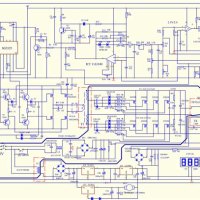
100w Inverter Circuit Schematic Diagram

Xd 30112 China Best Power Inverter Circuit Diagram Pure Sine Wave Dc 12v Manufacturer Supplier Fob Is Usd 1 0 1000 Piece

7 Simple Inverter Circuits For Newcomers

3 Best Transformerless Inverter Circuits Homemade Circuit Projects
What Is An Inverter Circuit Diagram Using Mosfet And Its Function Quora

Simple Sinewave Inverter Circuits
Inverter Circuit Diagram Simple For Pc Windows 10 8 7 Appsforwindowspc
Simple Inverter Circuit Diagram Android App

Schematic Circuit Diagram Of The Proposed Mli Using Gwo And De Scientific

Switching Transformerless Dc Ac 12v 230v 150w Modified Sine Wave Inverter

Make Simple 555 Inverter Circuit Using Mosfet Eleccircuit Com

1500 Watt Pwm Sinewave Inverter Circuit Homemade Projects

Circuit Makes Simple High Voltage Inverter Edn

Inverter Circuit Page 2 Power Supply Circuits Next Gr

6 Best Simple Inverter Circuit Diagrams Diy Electronics Projects


