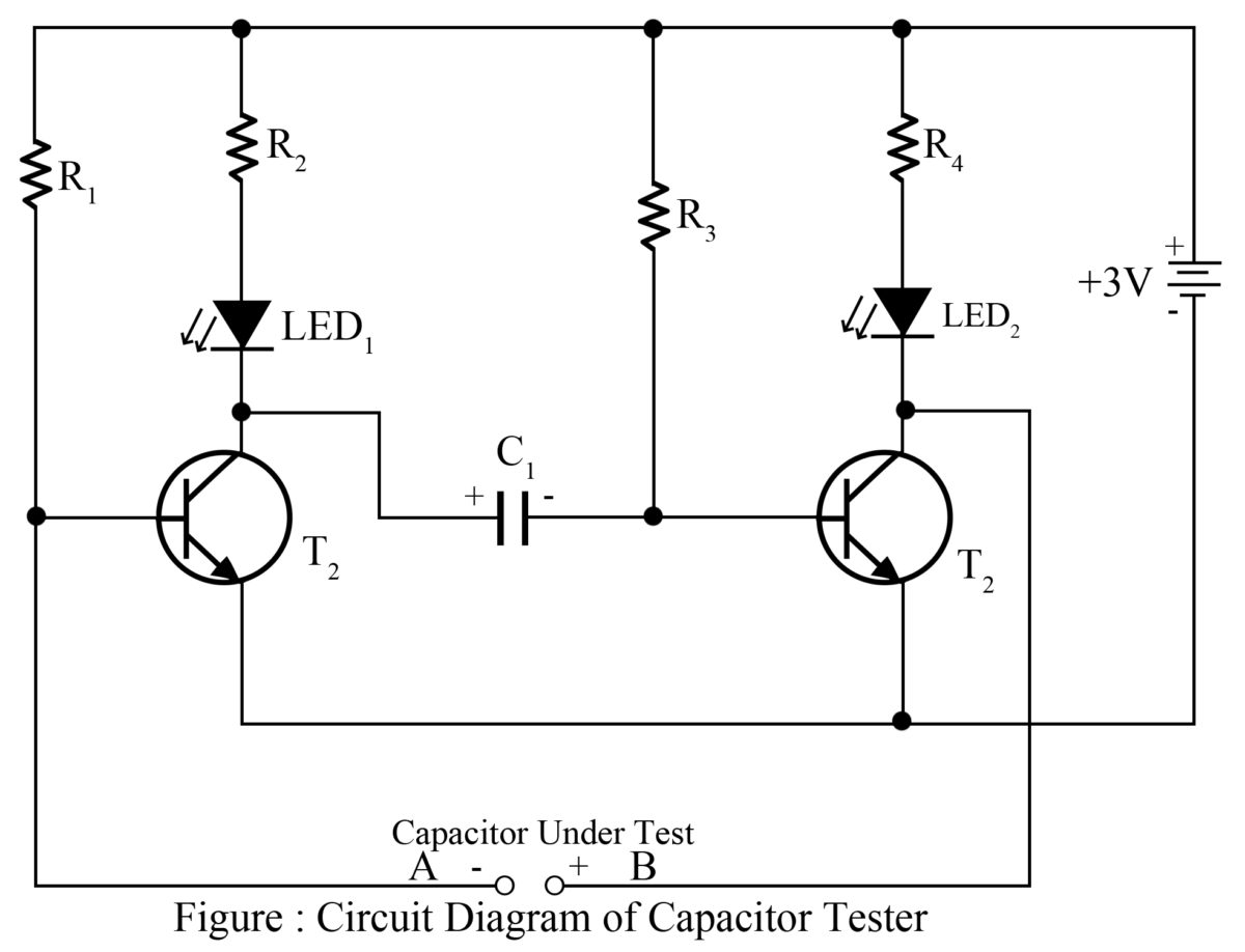
A capacitor tester circuit diagram is a useful tool for anyone looking to understand how capacitors function. With this circuit diagram, technicians and engineers can easily see the components of the circuit and how they interact with each other. This information allows for an improved understanding of the electrical properties of capacitors and how to design them correctly.
Capacitors work by storing electric charge in an electrostatic field. When a voltage is applied to the capacitor, it stores electric charge in its plates and then releases it slowly as electric current. This process is fundamental to many electronic devices, such as radios, TVs, and computers. Therefore, it’s important to understand how capacitors are designed and how they behave when used in circuits.
The capacitor tester circuit diagram provides a visual way to analyze the behavior of a capacitor in a circuit. It displays the components of the circuit, such as the capacitors, resistors, transistors, and other components, as well as their interactions. By studying the diagram, technicians can understand how capacitors respond to different voltages and under various conditions. Additionally, the diagram can reveal any problems with the circuit, such as a shorted capacitor or faulty wiring.
The capacitor tester circuit diagram is a valuable tool for any technician, engineer, or hobbyist looking to improve their understanding of capacitors and related circuitry. By studying the diagram, one can learn how different electrical components interact with each other and how to design circuits that best meet the needs of the user. Furthermore, the diagram is also a great way to spot potential issues or problems with a circuit before any damage or faults occur.

Capacitor Tester Flasher Engineering Projects

Solved Draw A Simplified Version Of Your Circuit Diagram For Chegg Com

Simple Capacitor Tester Circuit

Flyback Transformer Tester Circuit Using 2sc828

Matchbox Capacitor Tester Radioradar

Jingyan M6013 Autoranging Capacitor Tester Electronics Repair And Technology News

Capacitor Esr Meter Electronic Circuit Diagram

Op Amp Tester Circuit Diagram Very Easy Electronics Area

Capacitor Esr Meter

Esr Meter Electrolytic Capacitor Tester

Capacitor Leakage Tester Circuit Find Leaky Capacitors Quickly Homemade Projects

Simple Esr Meter Circuit Diagram

Capacitance Meter Electrical4u

Capacitor Leakage Adaptor For Dmms Circuit Diagram

Capacitor Leakage Tester Circuit Find Leaky Capacitors Quickly Homemade Projects

Oscilloscope Esr Tester
Diy Esr Meter Everything You Should Know About A

Simple Capacitance Measurement Circuit Using Ic 555

Analog Capacitance Meter Cd4013 Measuring And Test Circuit Diagram Seekic Com


