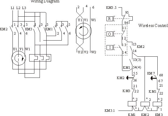
Controlling electrical wiring is a difficult task and one that requires a great deal of knowledge. This is especially true when dealing with the complexity of a star delta starter. Understanding how to read, interpret, and draw a control wiring diagram for a star delta starter can help make the process much simpler.
A star delta starter is a type of electrical motor starter that is used in heavy industrial applications. It is designed to reduce the current during the motor start up period. The diagram typically includes three contactors, an overload relay, a timer, and a pair of power contacts. When properly configured, the starter will cause the motor to start at low voltage and gradually increase in speed as the voltage is increased.
When reading a control wiring diagram for a star delta starter, it is important to understand the different components and how they interact. The most important part of the diagram is the contactors, which act as switches that turn on and off the power supply to the motor. The overload relay protects the motor from drawing too much power by sensing when it is overloaded and activating the contactors. The timer is used to control the frequency and duration of the contactor activation and helps prevent the motor from stalling.
Understanding the control wiring diagram for a star delta starter is essential for anyone who wishes to operate one safely and efficiently. With a proper understanding of the components and their interactions, it is possible to ensure the motor starts smoothly and runs without excessive strain or damage. By taking the time to understand the diagram, users can be sure they are using the motor correctly and safely.

Electro Mechanical Star Delta Starter Electrical Engineering Centre

Advantages And Disadvantages Of Star Delta Starter

Using Star Delta Motor Control With Circuit Diagrams Turbofuture

Motor Star Delta Starter Working Principle Instrumentationtools

Star Delta Starter Scientific Diagram
Wye Delta And Solid State Starters
Yk Electrical Star Delta Starter Control Wiring Diagram By Facebook Stardeltastarter Stardeltacontrolwiring Stardeltacontrolwiringdiagram Stardeltastartercontrolwiringdaigram

Star Delta Starter Circuit Y Δ How To Wire Pros And Cons

Schematic Of The Power Circuit Electro Pump Starter Via Automatic Scientific Diagram

Star Delta Starter Circuit Y Δ How To Wire Pros And Cons

Star Delta Starters Explained The Engineering Mindset

What Are Diffe Types Of Motor Starting Methods

Star Delta Starter Design Tool Wye

Products Star Delta Reduced Voltage Starter Lc3 D

Star Delta Soft Start Vfd How To Make The Smooth Of E Motor Vessel Automation

Plc Ladder Program Example Of Star Delta Starter Tutorial Point


