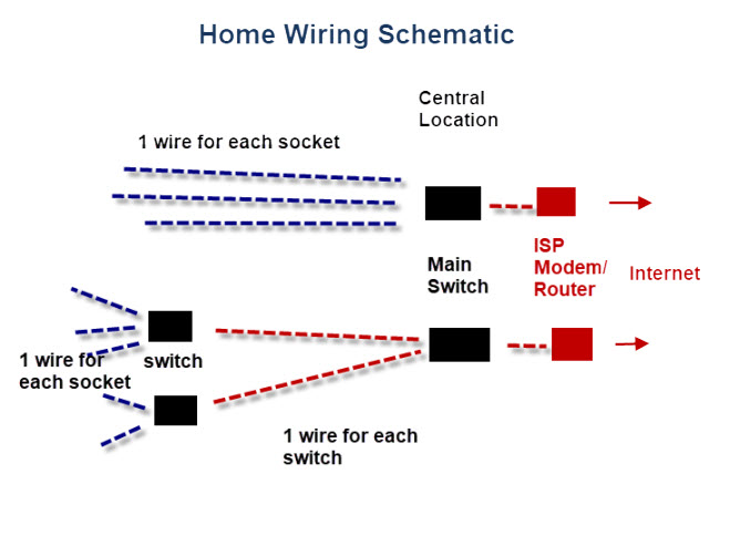
An understanding of a home run wiring diagram is essential for any homeowner who wishes to safely and correctly wire their home. Home runs are an important part of any electrical system, as they enable power to be directed efficiently and safely to the various outlets and fixtures throughout the house. With a home run wiring diagram, homeowners can easily recognize the various components of their electrical system and make the necessary adjustments to safely meet the needs of the household.
A home run wiring diagram typically consists of three main components: the breaker box, the wiring, and the fixtures and outlets. The breaker box is the central control center for the electrical system, regulating the power that is sent to each outlet and fixture. The wiring portion consists of two parts: the cables and the conduit. The conduits are used to protect the electrical wires from moisture, sunlight, and other external elements, while the cables are used to direct the power to the various outlets and fixtures.
Once the basic components of the home run wiring diagram have been identified, homeowners can begin to make the necessary changes to the electrical system. It is important for homeowners to accurately label all the wires, both in terms of color and number. This will allow them to identify the power source of each outlet or fixture, and make the necessary adjustments accordingly. Additionally, by labeling the wires and circuits, homeowners can quickly identify any potential issues and take steps to rectify them.
Finally, it is important for homeowners to conduct regular inspections of their home run wiring diagram to ensure its accuracy and safety. Inspections help to detect any worn or damaged wires, as well as identifying any new components that need to be incorporated into the system. Homeowners should also periodically test the circuit breaker to ensure that it is working properly. By taking these simple steps, homeowners can maintain a safe and secure electrical system for their home.

Diy Home Telephone Wiring

Pdf Inverter Ground Fault Detection Blind Spot And Mitigation Methods
Residential Telecommunications Wiring Primer Gohts Wiki

Greg Ercolano S Com Key 416 Page

Ac Capacitor Wiring Diagram And Connection Procedure Etechnog

How To Map House Electrical Circuits
Solved For The Home Run Hb 1 3 5 Shown Please Use Chegg Com

Wiring Diagrams

How To Wire A 4 Way Light Switch With Wiring Diagram Dengarden

Common Wiring For Dcc And Other Systems

Impedance Measurement Of Array Positive Home Run Wiring Through Scientific Diagram

Wire Tick Marks And Arrowheads Autodesk Community Revit Products

Guidelines To Basic Electrical Wiring In Your Home And Similar Locations

How To Wire A 3 Way Switch Wiring Diagram Dengarden

How Good Are You At Reading Electrical Drawings Take The Quiz Eep

How To Wire A 3 Way Switch Wiring Diagram Dengarden

How To Install Cabling In A Pre Built Home With Pictures

Wiring A Home Ethernet Network Practical Beginners Guide


