Creating circuit diagrams is one of the most important skills for any electrical engineer. To do it right, you need to understand the fundamentals of how a logic gate works and how to draw a logic gate circuit.
A logic gate is an electronic device that takes one or more inputs and produces one output that depends on the state of its inputs. The outputs of a logic gate may be either high or low (1 or 0). To draw a logic gate circuit, you need to know the symbols used to represent each gate type and how they are connected together.
The first step in drawing a logic gate circuit is to select the type of gate you want. There are several types of logic gates, such as AND, OR, NOT, NOR, and NAND. After selecting the type of gate, you should determine the inputs and outputs of the circuit. Once you have identified the inputs and outputs, you can draw the circuit according to the schematic diagram provided by the manufacturer.
When connecting logic gates together, the first step is to draw the connections between the inputs and the outputs. Once you have done this, you can then connect the logic gates together using wires or connectors. It is important to remember that logic gates must have the same number of inputs and outputs so that all of the gates function correctly.
Finally, you need to check the circuit diagram to make sure it is correct and that all of the gates are properly connected. After you have verified the correctness of the circuit diagram, you can power up the circuit and test it. This will help you identify any errors in the design and also give you an idea of how the circuit will behave in real-world applications.
Creating logic gate circuits requires knowledge and skill, but with practice, anyone can learn to make them. Knowing how to draw a circuit correctly can be the key to creating better designs and products. So, take the time to learn and practice the basics of how to draw a logic gate circuit and you will soon be creating complex and reliable electronic circuits.

Logic Circuits
How To Make A 3 Input Circuit Using Logic Gates That Will Only Activate If One Of The Outputs Is On Quora
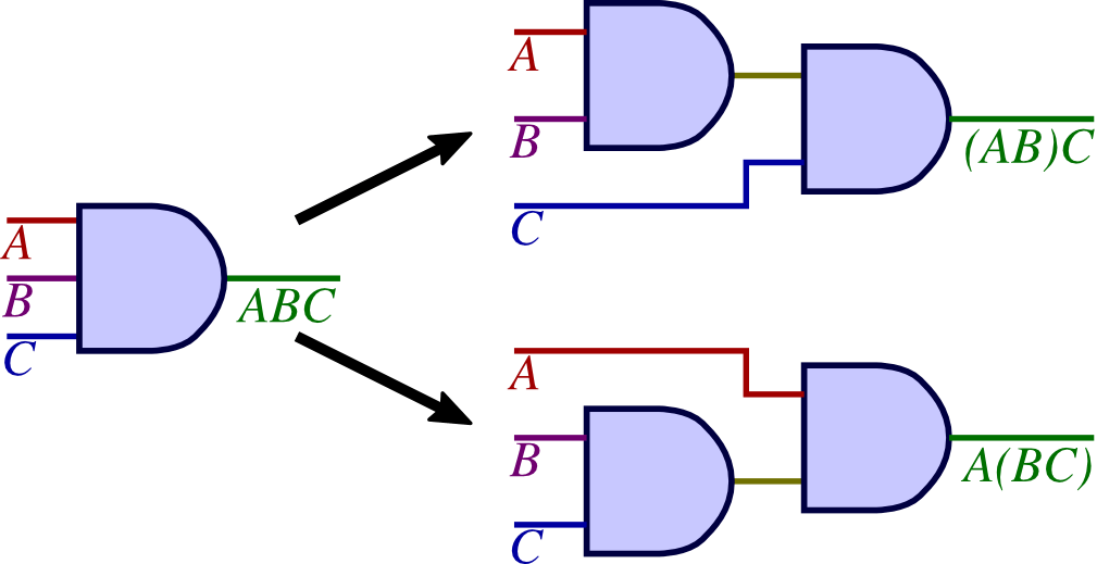
Logic Circuits
![]()
Circuit Simplification Examples Boolean Algebra Electronics Textbook

Logic Gate Examples

From Logic Gates To Registers Exploring The 74hc173
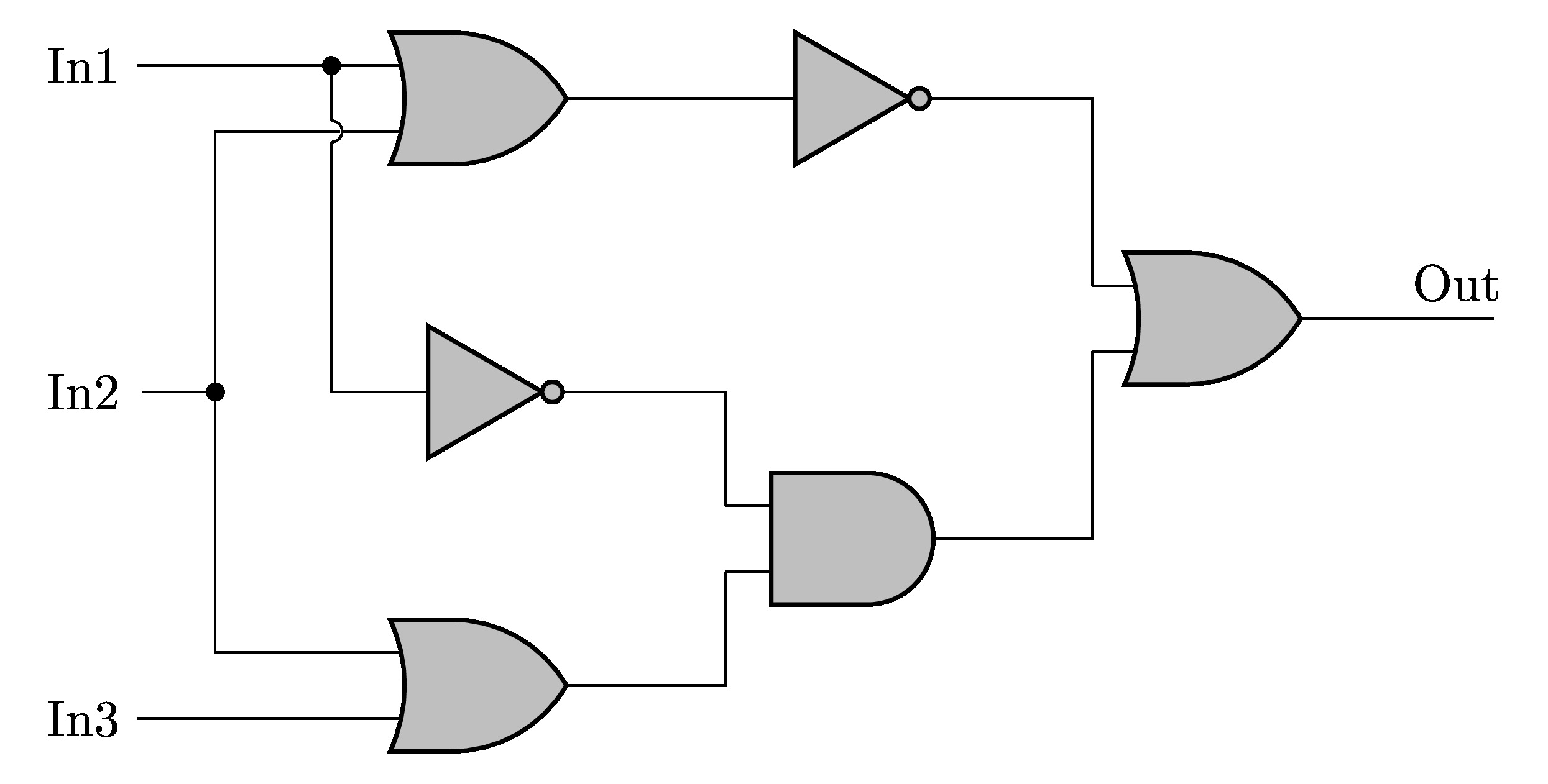
Draw A Logic Circuit In Circuitikz Tikzblog

Small Logic Gates The Building Blocks Of Versatile Digital Circuits Part 1 Nuts Volts Magazine

Designing An And Gate Using Transistors

Exam Questions Logic Gates Bits Of Bytes Co

Spotlight On Logic Circuits Technology For Learners

What Is Logic Diagram And Truth Table

Karnaugh Maps Truth Tables And Boolean Expressions Mapping Electronics Textbook
Lecture 11 Logic Gates And Boolean

Truth Tables Circuit Diagrams Of Logic Gates Your Electrical Guide

Logic Gate Software Tool Create Gates Online Creately
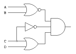
Logic Gate Examples

Digital Circuits Two Level Logic Realization

Logic Gates

Circuit Simplification Examples Boolean Algebra Electronics Textbook

