In the world of electronics, logic gate circuit diagrams provide essential information for designing and troubleshooting circuits. Logic gates are fundamental building blocks of digital circuits, and understanding how to read and interpret a logic gate circuit diagram is a key element in many types of engineering projects. This article will provide an overview of what logic gate circuit diagrams are, explain how they work, and discuss several common features of these diagrams.
Logic gates are electronic switches that are used to control the flow of electricity through a circuit. The most basic type of logic gate is the AND gate, which requires both inputs to be true in order for the output to be true. Depending on the type of logic gate, there can be two, three, or more inputs, with the output being determined by the relationships between those inputs. Logic gates can also be combined to create more complex circuits, such as those found in computers and other digital devices.
Logic gate circuit diagrams provide a visual representation of how the logic gates in a circuit are connected. These diagrams typically consist of symbols for each of the logic gates, as well as connecting lines that indicate the flow of electricity from one logic gate to another. There are several standard conventions for how logic gates are represented in a diagram, such as the logic gate symbol for an OR gate being the same regardless of the number of inputs.
In addition to the logic gate symbols and lines, logic gate circuit diagrams also contain other elements to help convey additional information. These can include arrows indicating the direction of the current flow, labels for each of the inputs and outputs, and color coding to denote the type of logic gate. This makes it easier to quickly interpret the logic gate circuit diagram and identify any potential issues that may exist within the circuit.
By taking the time to understand and interpret logic gate circuit diagrams, engineers and technicians can design and troubleshoot digital circuits with greater accuracy and efficiency. The ability to interpret these diagrams is a critical skill for anyone working in the electronics industry, and provides a great foundation for understanding how to design and troubleshoot digital circuits.

Truth Tables Circuit Diagrams Of Logic Gates Your Electrical Guide

Logicblocks Experiment Guide Learn Sparkfun Com
Teaching Digital Logic Fundamentals Theory Simulation And Deployment Ni

Logic Gates Everything You Need To Know Free Hardware

Nand Gate With 3 Inputs Truth Table And Circuit Diagram Edumir Physics

Digital Logic Gates Electrical4u

Logic Circuits Computer Science Gcse Guru
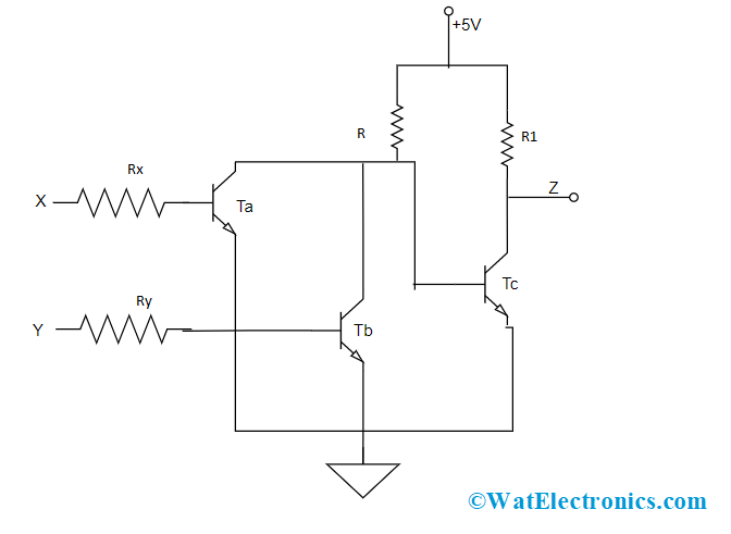
Or Gate Truth Table Circuit Diagram Functionality Its Applications
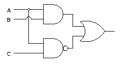
Logic Gate Examples

Cell Phone Controlled Land Rover Using Logic Gates
2 Bit Alu Logic Gate Diagram

Logic Circuits

Implementing A Full Adder With Dsc D Logic Gate Diagram Truth Scientific

Logic Gates

Xor Gate Circuit Diagram Using Only Nand Or Nor Edumir Physics

Digital Electronics Logic Gates Basics Tutorial Circuit Symbols Truth Tables

Logic Gates And Gate Or Nor Universal

Some Applications Of Logic Gates Springerlink
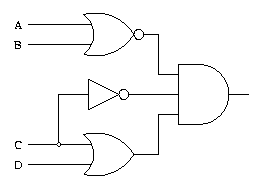
Logic Gate Examples


