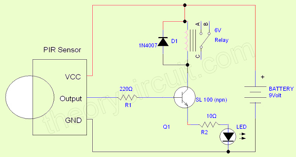
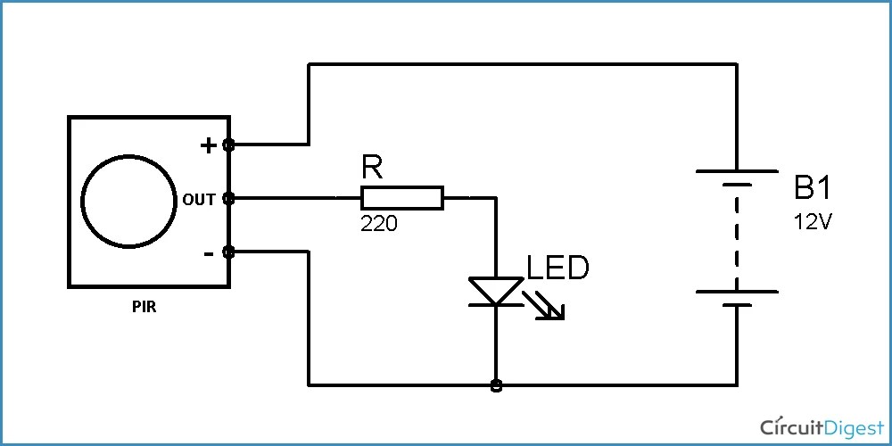
A pir switch circuit diagram is a simple, yet effective tool used to control the flow of electricity in a given system. This type of diagram is often used in security applications, providing the ability to detect motion and control the trigger of an alarm. At its most basic level, a pir switch consists of an infrared diode that detects light or curtains, an electronic switch, and a power source.
When a pir switch is activated, it sends a signal to the switch and then to the attached power source. The switch then triggers an electrical circuit that can be used to activate a set of lights, a sound alarm, or any other device. Unlike other security systems, a pir switch circuit diagram offers the advantage of being able to detect the presence of a person, even in low light levels. This makes it ideal for outdoor security applications.
The wiring of a pir switch is relatively straightforward. A basic circuit diagram consists of a power source, an infrared diode, and an electronic switch. From there, the diagram will then become more complex depending on the specific application. For example, additional components may be needed if the system requires sensing motion at different angles or distances.
Pir switches are a popular choice for home and business security solutions, as they offer the advantages of being both reliable and affordable. A properly installed and maintained pir switch can provide a reliable layer of protection against unwanted intruders. However, it is important to remember that the effectiveness of a pir switch depends largely on the quality of the installation. It is always best to consult with a professional electrician to ensure the system is properly wired and operating safely.

The Circuit Diagram For Capturing An Analog Output Signal From A Pir Scientific
Pir Motion Sensor Wiring And Connection Diagram For Installation Etechnog

Simple Pir Sensor Circuit

Motion Sensor Light Switch Using Cd4017 Ir With Circuit

Troubleshooting Pir Sensor And Sensitivity Adjustment Arduino Help Center
Wiring Pir Light Switch Diynot Forums

Pir Sensor Based Motion Detector Circuit Diagram

Motion Sensor Light Switch Using Cd4017 Ir With Circuit

Motion Activated Pir Relay Circuit

How To Build A Motion Detector Circuit

Pir Sensor Burglar Alarm System Circuit Using 555 Timer Ic Electroduino

Pir Motion Detector Control Circuit 325 Electronics Projects Circuits

Motion Sensor Circuit For Security Light Detailed Project Available

Motion Sensor Wiring With Switched Override Feature

Motion Detector Alarm Circuit With Pir Sensor Simple And Cheap

Pir Sensor Circuit And Working With Applications
Pir Motion Sensor Relay On Off Circuit Soldering Mind
Motion Sensor For Security Light Using Pir Bs1600 Pcb Under Repository Circuits 36560 Next Gr


