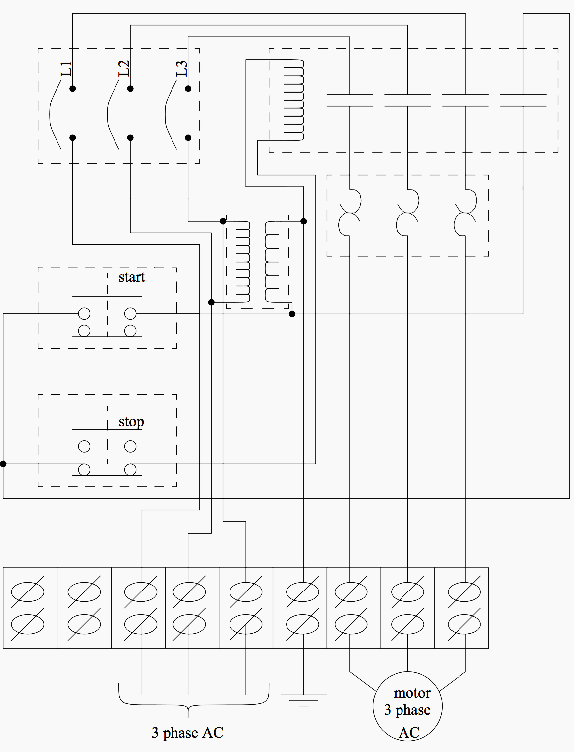
When it comes to industrial automation, wiring diagrams are a critical component of the overall system. PLC control wiring diagrams are no exception. They provide the information necessary for connecting programmable logic controllers (PLCs) in distributed control systems. In this article, we'll explore what a PLC control wiring diagram is, how they can help technicians troubleshoot, and how they are used in the industrial automation industry.
A PLC control wiring diagram outlines the electrical connections needed to operate a PLC in an automated system. It includes the wiring diagrams for both the power supply and the I/O modules, as well as the necessary control cables. In addition to providing the technical details, PLC control wiring diagrams also indicate the locations of each component in the system. This is done to ensure that the system remains organized and easy to use.
Having a detailed PLC control wiring diagram is invaluable for technicians when troubleshooting a system. This is because it provides an overview of the entire system and helps pinpoint where the problem may be located. Being able to quickly identify potential problems greatly reduces downtime and ensures that the system operates efficiently.
PLC control wiring diagrams have been used in the industrial automation industry for decades. They are often used in conjunction with other control systems such as SCADA, HMI, and DCS. The ability to connect multiple control systems in a single wiring diagram allows technicians to easily create large, complex systems without having to build separate diagrams for each component.
Overall, PLC control wiring diagrams are essential for industrial automation systems. By providing all the necessary details, they make troubleshooting much easier, reduce downtime, and allow technicians to create more complex systems. For anyone involved in industrial automation, having a detailed PLC control wiring diagram is invaluable.

Sequential Motor Control Circuit 3 Diagrams With Switch Timer Plc

How To Read An Electrical Wiring Diagram Inst Tools

Electrical Panel Wiring Diagram

Wiring Design Electrical Circuit Schematics Solid Edge

Simple Plc Program For Lighting Control System

How To Communicate Plc Vfd

How To Read A Plc Wiring Diagram Control Panel Upmation

Plc Wiring Example Engineers Community

Plc Wiring Vfd Skills Hands On Electrical Training Amatrol

External Wiring Diagram Of Plc Under Other Circuits 58663 Next Gr

Plc Wiring Diagram P Pump M Motor T92s11d22 12 And Kuhp 11d51 Scientific

Wiring In A Plc Control Panel Basic Electrical Design

Plc Control Systems Automation Introduction

Programmable Logic Controllers Plc Ladder Electronics Textbook

Experimental Circuit Wiring Diagram For Programmable Logic Controller Scientific

How To Read A Plc Wiring Diagram Control Panel Upmation

Basic Electrical Design Of A Plc Panel Wiring Diagrams Eep

The Wiring Principle Circuit Diagram Of Plc Control Pump Motor Seekic Com


