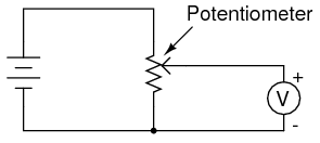
A potentiometer circuit diagram and its working are important for electrical and electronics engineers to understand, as it is often used in applications such as voltage dividers, power supplies, and many other analog applications. A potentiometer is a variable resistor which works by changing resistance to adjust current or voltage, and the circuit diagram is used to illustrate how this is achieved.
A potentiometer consists of three terminals, with the wiper terminal, the middle terminal, connected to the slider which can be adjusted manually to increase or decrease resistance. The two outer terminals are connected to either side of the resistor; when the wiper is moved, the resistance across the resistor is changed. The voltage across the resistor then changes, and this is what is used to control current or voltage.
The circuit diagram of a potentiometer is simple, showing just the three terminals and their connections. However, the setup of the circuit must be taken into account when creating a successful potentiometer circuit. As resistance from the wiper terminal to the outer terminals changes, the voltage across the resistor changes accordingly, so the resistor should be placed in such a way that the ratio of resistance to the wiper terminal is proportional to the voltage drop.
When it comes to applications, a potentiometer circuit can be used to create an adjustable voltage. This could be used to supply power to an electronic device, or to adjust the output voltage of a power supply to the desired level. Potentiometers are also used for volume control for audio systems, and for adjusting the speed of motors.
The use of a potentiometer circuit diagram and its working principles can be very important for electrical engineers, as it allows them to create circuits in which the control of current and voltage is made easier and more efficient. As such, understanding the workings of a potentiometer and being able to easily interpret its circuit diagram can be very useful in many different scenarios.

Potentiometer Connection Circuit Diagram Wiring Guide Linquip

Chapter 6 Potentiometer Circuit Step By Arduino To Go

Ldr Circuit Diagram Build Electronic Circuits

Potentiometer Connection Circuit Diagram Wiring Guide Linquip

X9cmme Digital Potentiometer Circuit

Potentiometer Working Circuit Diagram Construction Types

State The Working Principle Of Potentiometer Explain With Help Circuit Diagram How Emf Two Primary Cells Are Compared By Using Snapsolve

Solved 15 C In The Circuit Diagram Potentiometer Chegg Com

Potentiometer Construction Types Working Applications

Potentiometer Arduino Tutorials
Solved For The Linear Displacement Potentiometer Circuit Chegg Com

What Is Potentiometer Pot Definition Characteristics Construction Working Circuit Globe

Potentiometers Rheostats And Trimmers

What Is Linear Potentiometer Working Diagram Explanation Electricalworkbook

How To Connect A Potentiometer In Circuit

L4 Potentiometers Physical Computing

Sik Experiment Guide For Arduino V3 2 Learn Sparkfun Com

Schematic Diagram Of The A Digital Potentiometer And B Low Pass Scientific

What Is Potentiometer Diagram Working Advantages

Solved 15 Cin The Circuit Diagram Potentiometer Chegg Com


