A potentiometer circuit diagram is a schematic representation of an electrical component used to measure or adjust the amount of resistance in a circuit. The circuit diagram contains a series of symbols that represent different components, such as resistors, capacitors, and switches. These components are connected together to create a complete circuit that can be used to measure or adjust the amount of resistance across the entire system.
Potentiometer circuits are commonly used in a variety of applications, such as controlling the volume of audio equipment or adjusting the brightness of lights. They can also be used to control the speed of a motor or to regulate the temperature of a space. In all of these cases, the circuit diagram provides a schematic representation of the component and its associated connections.
The diagram will usually display the component's name in a large font, along with a description of its function. It will then have a series of lines connecting the component with other circuit components, such as resistors, capacitors, and switches. The diagram will also include arrows to indicate the direction of current flow within the circuit. Once everything is connected correctly, the circuit diagram allows engineers to easily understand how the component works and what effect it will have on the system as a whole.
To ensure that the diagram is accurate and effective, engineers must always adhere to a set of standard symbols and conventions for drawing a potentiometer circuit diagram. Each component must be represented accurately, with all of its associated connections being clearly identified. Additionally, the arrows must be drawn in the correct direction to indicate the flow of current and any additional labels should be included to help engineers understand the circuit’s function. By adhering to these guidelines, engineers can ensure that the circuit diagram accurately reflects the component’s properties and that the circuit will perform as intended.

Potentiometer Working Circuit Diagram Construction Types

Arduino 读取模拟电压 爱资料工具
Potentiometer Taper Charts Antique Electronic Supply
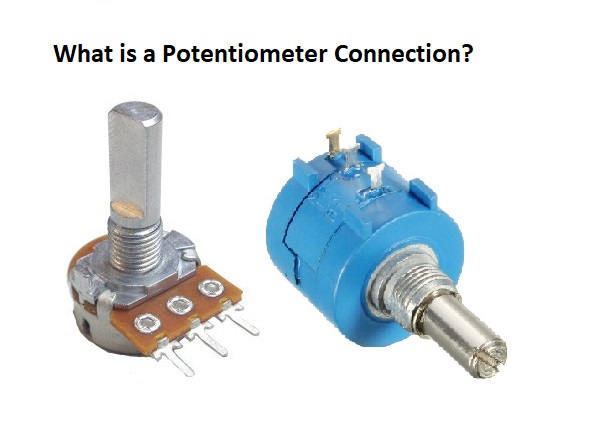
Potentiometer Connection Circuit Diagram Wiring Guide Linquip

Working Principle Of Dc Potentiometer With 6 Applications

Remote Controlled Potentiometer Electronics Projects Circuits

The Potentiometer And Wiring Guide Build Electronic Circuits

Potentiometer Working Principle With Their Types And Applications

Potentiometer As A Rheostat Dc Circuits Electronics Textbook

What Is Potentiometer Pot Definition Characteristics Construction Working Circuit Globe

State The Principle Of Potentiometer Draw A Circuit Diagram To Compare Emf Two Primary Cells Write Formula How Can Sensitivity Be Increased From

How To Read A Schematic Learn Sparkfun Com

A Potentiometer Circuit Is Shown In Figure 3 Below Ab Uniform Metallic Wire Having Length Of 2m And Resistance 8omega The Batteries E 1 2 Have Emfs 4v

Sparkfun Inventor S Kit Experiment Guide V4 1 Learn Com

Chapter 6 Analog Values Arduino To Go
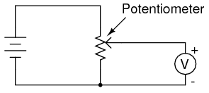
Potentiometer Arduino Tutorials

A Potentiometer Schematic Circuit Diagram Scientific

Potentiometer Construction Types Working Applications
Solved For The Potentiometer Circuit In Experiment 1 Step 6 Figure 3 Course Hero


