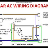
A schematic diagram of a simple electrical circuit is an essential tool for any electrician or engineer. It allows them to understand the relationship between the various components of the circuit, and how they interact with each other. It can be used as a blueprint for building a circuit, or as a reference guide when troubleshooting a problem. In this article, we will explore the basics of how a schematic diagram of a simple electrical circuit is drawn and represented.
The first step in creating a schematic diagram is to draw a basic outline of the circuit. This includes the power supply, the connections between components, and the components themselves. The most common type of schematic diagram is the electrical wiring diagram, which shows the connections between the components and the wiring. Once the basic outline is established, the electrical connections can be drawn in detail. This includes the power sources, the switches, and the different types of wires.
Once the wiring is set up, it’s time to add the symbols that represent each component. The symbols can be designed to represent either active or passive components. Active components are typically switches, resistors, or transistors. Passive components, on the other hand, are usually capacitors or inductors. Each symbol should be clearly labeled, so that it can be easily identified by other engineers and electricians.
Finally, the schematic diagram should also include labels for the various connections. These labels should be clear and concise, so that anyone looking at the diagram knows exactly which connections they are referring to. Labels should also be used to indicate whether the connection is positive or negative. If it’s not obvious, the label should provide an explanation. Labels should also be used to help identify any special warnings or restrictions that may apply to the particular circuit.
Creating a schematic diagram of a simple electrical circuit is an important skill for any electrician or engineer. It allows them to easily understand the relationship between the components and how they interact with each other. It can be used as a blueprint for building a circuit, or as a reference guide when troubleshooting a problem. With the help of this article, you now have a better understanding of how a schematic diagram of a simple electrical circuit is drawn and represented.

Plc Training Reading Electrical Wiring Diagrams And Understanding Schematic Symbols Tw Controls

Physics Tutorial Circuit Symbols And Diagrams
What Is The Difference Between Schematic Diagram And Wiring For Electrical Connections Quora

Wiring Diagram A Comprehensive Guide Edrawmax Online

Circuit Diagram Before Pcb Design Manufacturing Assembly Madpcb

Resources

L2 Circuit Schematics Physical Computing

Schematic Diagram Of Electrical Circuit Examined Machine Scientific

Physics Tutorial Circuit Symbols And Diagrams

Electrical Diagrams And Schematics Inst Tools

How To Read Electrical Schematics Circuit Basics

Circuit Diagram And Its Components Explanation With Symbols

Electrical Drawings And Schematics Overview Articles Testguy Testing Network

Why Do We Need Electrical And Electronic Symbols Are Important Automation Plc Programming Scada Pid Control System

What Is The Meaning Of Schematic Diagram Sierra Circuits

Electronic Drafting


