A typical PLC wiring diagram is the foundation of a successful automation system. Understanding how to read and interpret one can help to ensure that you get the most out of your system and avoid costly errors.
A typical PLC wiring diagram is composed of symbols representing components and connections between them. The diagram is a visual representation of the system’s logic, and it can be used to identify potential problems and diagnose issues. PLC wiring diagrams often come with additional information, such as naming conventions and pin assignment conventions, which are essential for understanding the diagram.
To read a typical PLC wiring diagram, start by looking for the different components represented by the symbols on the diagram. Identify all connections between the components and note the direction of the connections. Then look for any safety features and make sure that all components are connected in the proper order. Finally, take note of any power requirements, such as voltage and amperage, and double-check that all connections are secure.
When reading a typical PLC wiring diagram, it is important to remember to look for potential errors and double-check connections. This can save time and money in the long run, and will help to ensure the system is safe and functioning properly. With a bit of practice, understanding and interpreting a typical PLC wiring diagram can become second nature, allowing you to get the most out of your automation system.

Electrical Panel Wiring Diagram

Chapter 6 Wiring Techniques

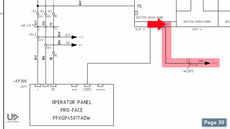
How To Read A Plc Wiring Diagram Control Panel Upmation

How To Read A Plc Wiring Diagram Control Panel Upmation

How To Connect A Solenoid Valve With Plc Instrumentationtools

Basic Electrical Design Of A Plc Panel Wiring Diagrams Eep

Plc Controls A Solenoid Valve With Relay

Plc Wiring Diagram Scientific

Plc Analog Signals Wiring Techniques Circuits

How To Read A Plc Wiring Diagram Control Panel Upmation

Plc Controls A Solenoid Valve With Relay

How To Read A Plc Wiring Diagram Control Panel Upmation

Wiring An Allen Bradley Micro820 Plc Inputs And Outputs Or A Micro800 Micro830 Micro850 Micro870 Tw Controls

Experimental Circuit Wiring Diagram For Programmable Logic Controller Scientific

Wiring Plcs

Typical Wiring Diagram When Deep Sea Electr Manualzz

Plc Hardware Components Specifications Wiring Connection

A Circuit Diagram Is The Key To Electrical Electronic Equipment And Systems

Plc Wiring Diagrams Digital Signals Techniques


