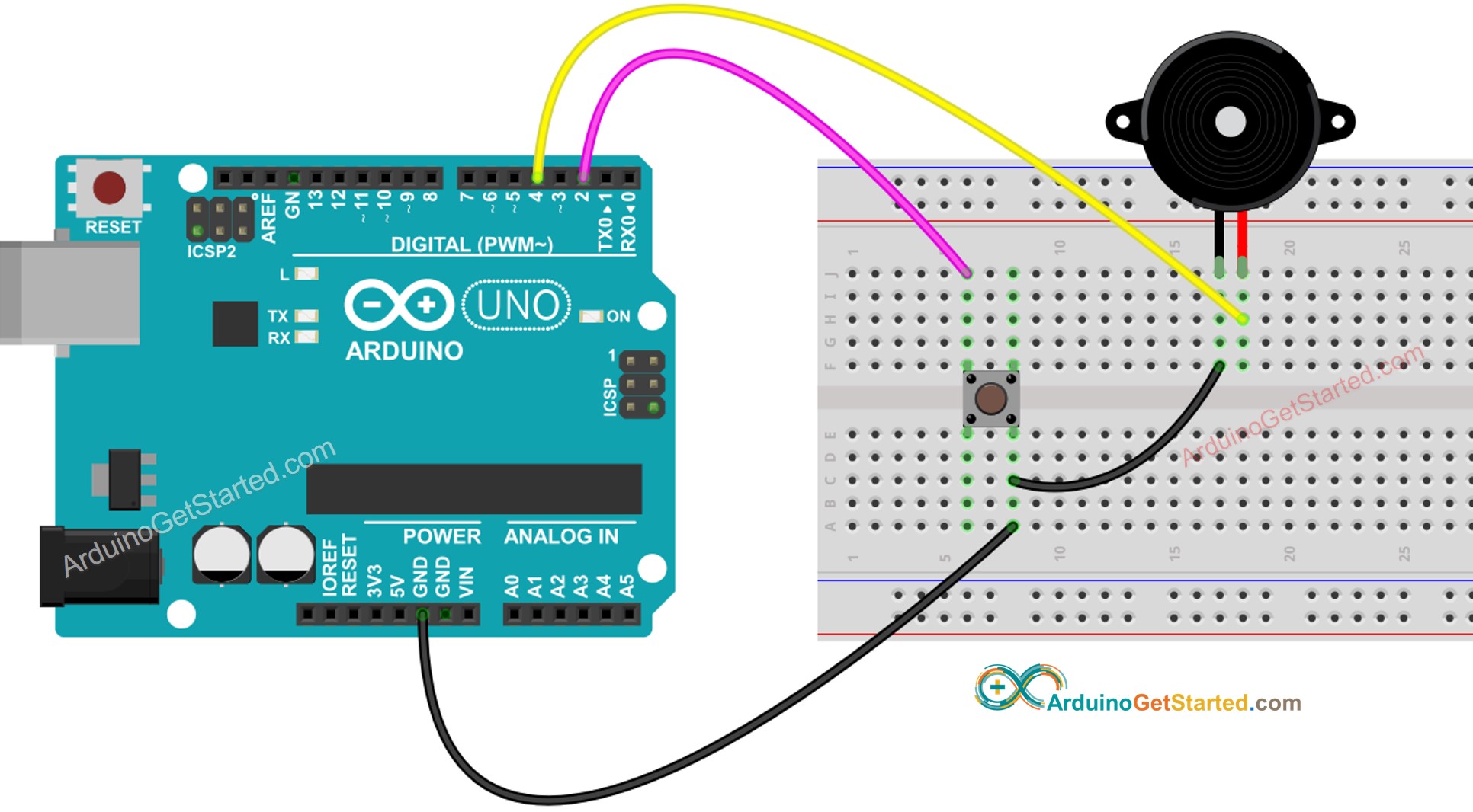
Wire Buzzer Game Circuit Diagram is a great way to create an interactive and fun game for family and friends. It also allows you to explore circuit design, construction, and troubleshooting. The wire buzzer game circuit diagram provides an easy-to-follow guide for creating a game using just a few components such as a power source, switches, and resistors.
The wire buzzer game circuit diagram is designed to work with most standard power sources, including batteries and AC power supplies. This makes it easy to construct and maintain the circuit. The circuit works by having two players press two of the switches simultaneously while the buzzer sounds. The first to press their switch will light up the indicator.
The wire buzzer game circuit diagram includes a detailed set of instructions on how to assemble the circuit. Step-by-step diagrams make it easy to understand the components and wiring. Once the wiring is complete, the game can be tested by connecting the power source and pressing the switches. After the game has been tested it can be adjusted to set the difficulty level or the number of players.
The wire buzzer game circuit diagram also provides instructions on troubleshooting in case something goes wrong. This makes it easy to identify and fix any issues that may arise during play. The wire buzzer game circuit diagram can also be modified for different levels of difficulty or additional components can be added for an even more creative and challenging game.
Overall, the wire buzzer game circuit diagram is a great way to learn about electronics and have some fun. The circuit is easy to follow and build, and the game provides hours of educational entertainment. So, if you are looking for a fun activity that allows you to explore circuit design and build a simple game, the wire buzzer game circuit diagram is an ideal option.

Make A Buzz Wire Game With An Arduino

Wire Loop Game Using Transistors Diy

Game Electronic Circuit Page 5 Other Circuits Next Gr

Game Circuits

School College Quiz Buzzer Circuit Diagram Using 555 Timer Ic

Make A Buzz Wire Game With An Arduino
Broken Charger Wire Alarm Circuit

Whats The Third Wire On A Piezo Buzzer Under Repository Circuits 25791 Next Gr
Willerby Carr Lane Primary School Science Topic Electricity Year 6 Strand Physics

The Thyristor Breadboard Circuit

Electronics Circuits Module 4 2 Proudly Developed By

Game Circuits

Arduino On Piezo Buzzer Tutorial

Electricity Applications

Game Circuits

How To Make Buzz Wire Game Hackaday Io

Wire Loop Game Using Transistors Diy

Buzz Wire


