Wiring Diagrams of PLC Panels – What You Need to Know
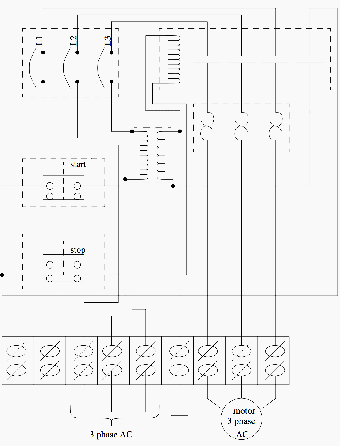
PLC (Programmable Logic Controller) panels are a critical component of industrial automation systems, responsible for controlling and automating processes. These systems are made up of several components that must be connected properly to function as designed. The wiring diagram of the PLC panel is an important tool for engineers who work on these systems, as it helps ensure a proper connection between the various components.
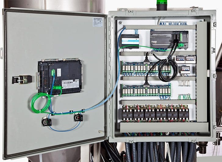
Understanding wiring diagrams of PLC panels can be overwhelming for those who are unfamiliar with them. Luckily, there are many resources available to help engineers better understand how these diagrams work. First, it’s important to have a basic understanding of the components that make up a PLC panel. Generally, these include the power supply, input/output modules, and the processor. The power supply provides electricity to the system, while the input/output modules connect the system to outside sources, such as sensors or other machines. Finally, the processor coordinates the panel’s operations based on the commands from the user.
Before attempting to work with a PLC panel, it’s important to understand the wiring diagram. Each component of the panel is printed on the diagram with clearly labeled wiring schematics. It’s essential to pay attention to the polarity of each connection, as well as the voltage ratings of the various components. Wiring diagrams also help engineers identify any potential problems with the panel before it is used in production. This prevents costly errors that could lead to damage or downtime.
When working on PLC panels, it’s important to adhere to the wiring diagrams provided by the manufacturer. Inaccurate diagrams can lead to incorrect connections, malfunctioning components, and ultimately, safety issues. It’s also important to note that wiring diagrams can differ depending on the model and brand of the panel. Make sure you use the correct diagram for your specific system and double-check the connections before putting the panel into service.
In conclusion, understanding wiring diagrams of PLC panels is essential for engineers who work with industrial automation systems. These diagrams provide the necessary information for connecting components correctly and safely. They also help identify any potential problems during setup and are typically supplied by the manufacturer. By adhering to the diagrams, engineers can ensure the safety of their systems and avoid costly errors.

Plc Control Panel Wiring Archives Upmation

Sipro Tech Switchboard And Control Panel Design Service
What Is Power And Control Wiring

How To Communicate Plc Vfd

Control Panel Engineered Services Horlick

Aim Manual Page 54 Single Phase Motors And Controls Motor Maintenance North America Water Franklin Electric

Design Your Control Panel And Make Wiring Diagrams By Tecogrp Fiverr

Small Sel Generators Wiring Diagrams

Self Adhesive Wiring Diagram For Control Panel Rangvishwa Enterprises Id 10541553097

Intelligent Electrical Control Panel Design Siemens Digital Industries Software

Basic Electrical Design Of A Plc Panel Wiring Diagrams Eep

Pdf Design Assembly And Testing Of Hvac Electrical Panel

Plc Wiring Diagrams Digital Signals Techniques

Afcs Control Panel Wiring Diagram

Basic Electrical Design Of A Plc Panel Wiring Diagrams Eep
A Condensed Guide To Automation Control System Specification Design And Installation

How To Read A Plc Wiring Diagram Control Panel Upmation

The Basics Of Reading Plc Panels And Wiring Diagrams Do Supply Tech Support

Can I Bus Wiring And Pneumatic Diagrams Ska Fab Depalletizers Conveyance Systems


