Wiring schematics are a crucial part of understanding electricity and electrical systems. Without them, troubleshooting and repair can be difficult and even dangerous. But what are wiring schematics, and how do they work? Let's take a look.
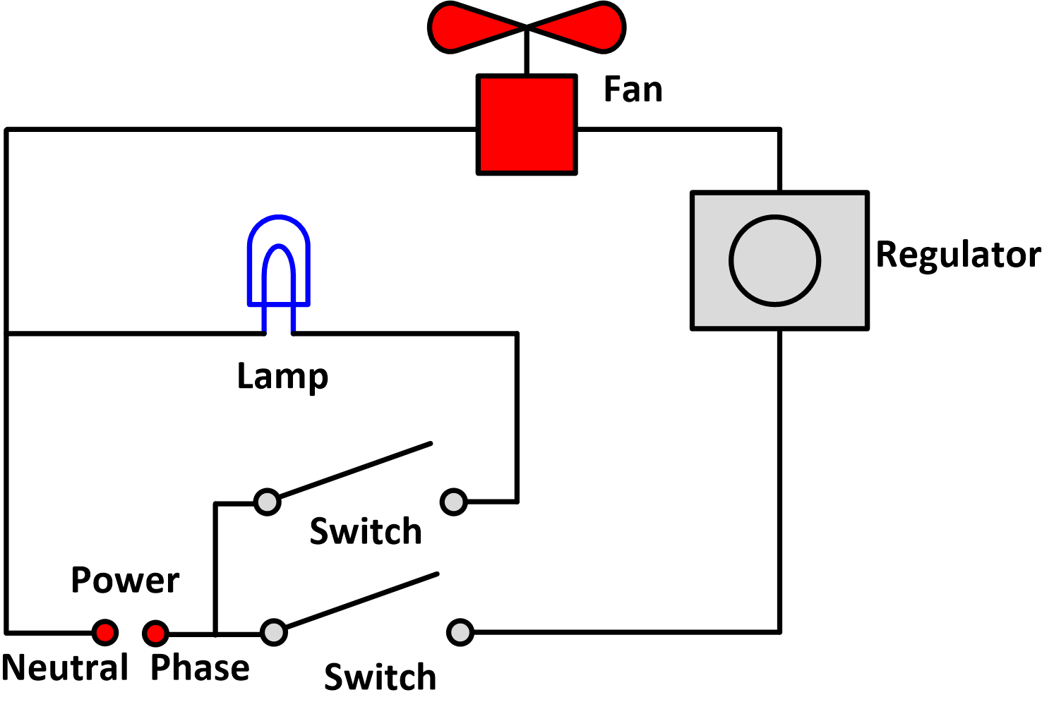
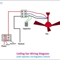
A wiring schematic is a diagram that shows the electrical connections in a given system, including the relationship between components and the power source. Every component is labeled in the schematic, allowing technicians to identify its exact role in the larger electrical system. It also includes details about the exact type of current used and the amount of voltage for each connection. These schematics are often included with manuals for complex electrical systems so technicians can easily identify and diagnose problems.
While wiring schematics may appear complex at first, they are actually quite simple to understand once you get the hang of it. With just a basic understanding of electricity, you'll soon be able to read these diagrams like a pro. At the most basic level, each line on the schematic is a wire, and the arrows pointing toward or away from the power source (battery, generator, etc.) denote the direction of the current flow. By reading the diagram, you can trace the path the current takes from the power source to the various components. Once you can identify the components and how they're connected, you can easily troubleshoot and repair the system.
All in all, wiring schematics are an invaluable tool for technicians working with electrical systems. Understanding these diagrams can save time and money by allowing you to diagnose problems quickly and accurately. After a little practice, reading schematics can become second nature. So if you're dealing with electrical issues, take a few minutes to try and understand the wiring schematic. It just might save you a lot of trouble in the long run.

Electrical Panel Wiring Diagram

Wiring Diagram Everything You Need To Know About

Electrical Schematics How To Read 2 Relays Blog Related Automation Plc Hmi Control Systems

Electrical Drawings And Schematics Overview

What Is A Single Line Diagram How To Draw Circuit

What Is The Meaning Of Schematic Diagram Sierra Circuits

Wiring Diagrams Explained How To Read Upmation

Audio And Connections Explained Basic Diagramming How To Use House Electrical Plan Software Av Schematic Diagram

Electrical Wiring Diagram Of The Four Point Measurement Setup Scientific

Wiring Diagrams

How To Read A Schematic Learn Sparkfun Com

Understanding European Wiring Diagrams Thesamba Com

How To Read Car Wiring Diagrams Short Beginners Version Rustyautos Com

Electrical Drawings And Schematics Overview

Wiring Diagrams Explained How To Read Upmation

Ladder Diagram Schematic Wiring Electrical Academia

How To Read Electrical Schematics Circuit Basics

Electrical Symbols Gray Furnaceman Furnace Troubleshoot And Repair


